
Selecting the right Electric Gate Valve is rarely a simple catalog exercise. The correct choice depends on fluid type, pressure, temperature, pipe size, and operating frequency. A valve that works well with clean water may fail quickly in abrasive slurry. That detail matters.
Richard W. Greene, author of Valve Design Handbook, offered a useful reminder: “A valve is only as good as its application.” This principle should guide every purchase decision. The following seven tips examine practical selection points, including body materials, sealing performance, actuator torque, power supply, control signals, installation conditions, and maintenance access. These factors influence reliability more than appearance or initial price.
Field experience often reveals problems that product sheets do not show. A compact actuator may struggle when sediment increases gate resistance. A stainless-steel body may still suffer if the seat material is poorly matched. Check the actual pressure drop. Confirm the valve’s fail position. Measure available voltage at the installation point, not only at the control panel. Small oversights become expensive shutdowns.
No checklist is perfect. I have seen specifications change after engineers reviewed the real pipeline environment. That is why buyers should compare certified test data, inspection records, warranty terms, and supplier support. Ask how the Electric Gate Valve performs after repeated cycles, not only during factory testing. Consider spare parts, manual override access, and future automation needs. The cheapest option can become costly when removal requires cutting the pipe. Careful selection takes longer, but it usually protects safety, process stability, and total operating cost.
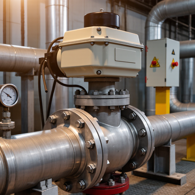
7 Tips for Choosing the Right Electric Gate Valve
Before selecting an electric gate valve, identify the medium, temperature, pressure, and flow direction. Water, steam, corrosive chemicals, and abrasive slurry create different sealing and material requirements. Record normal pressure and the highest startup pressure. Do not size from average readings alone. A valve exposed to 8 MPa during pump surges needs more margin than one operating steadily at 2 MPa. This detail is often missed. Keep it practical.
ASME Classes 150, 300, and 600 provide recognized pressure categories, but they are not fixed MPa equivalents at every temperature. Material grade and temperature change the allowable pressure. As a rough ambient reference, Class 150 may suit approximately 0.5–2 MPa, Class 300 about 2.5–5 MPa, and Class 600 about 6–10 MPa. These figures are only screening values. Check the exact pressure-temperature table before approval. A Class 300 valve may fail your specification for hot steam, even when its cold rating looks acceptable. Not enough.
Classify the medium by viscosity, solids content, corrosiveness, and cleanliness. Abrasive particles can damage seating surfaces during repeated operation. Choose the electric actuator according to shutoff differential pressure, operating frequency, and required torque. Confirm flange dimensions, shell-test pressure, enclosure protection, and local control needs. A quick spreadsheet can produce an optimistic answer. Recheck it against real startup conditions, especially when pumps, long pipelines, or thermal expansion are involved. One overlooked surge can change the selection.

7 Tips for Choosing the Right Electric Gate Valve
Choosing the correct electric gate valve starts with matching valve size to the pipeline and required flow. Sizes may range from DN15 to DN1200, so a visual estimate is unreliable. Measure the line. DN indicates nominal diameter, not always the exact internal opening. Review flow rate, pressure, temperature, and fluid properties before selecting the valve. A DN100 valve may suit one system but restrict another if the process requires higher capacity.
Full-bore design keeps the flow passage close to the connected pipe diameter. This reduces pressure loss and helps limit turbulence across the valve. It also allows smoother movement for liquids containing small suspended particles. In field inspections, oversized valves often create poor control signals and unnecessary actuator costs. An undersized valve can increase velocity, noise, and erosion. That assumption fails. Gate valves are generally intended for fully open or fully closed service, not regular throttling.
Electric actuator selection must match valve torque, operating frequency, and safety requirements. Large valves from DN300 to DN1200 may need higher starting torque, stronger mounting, and position feedback. Check flange standards and face-to-face dimensions before delivery. Site conditions matter too. Dust, moisture, outdoor exposure, and limited maintenance access can affect actuator reliability. I have seen projects specify the right DN size but overlook cable entry protection. The result was avoidable commissioning work. Leave room for manual override and future inspection.
| Nominal Size | Approx. NPS Equivalent | Nominal Bore (mm) | Indicative Flow at 1.5 m/s (m³/h) | Indicative Flow at 3.0 m/s (m³/h) | Typical Full-Bore Selection Guidance | Electric Actuator and Design Check |
|---|---|---|---|---|---|---|
| Small Pipeline Sizes: Instrument, Utility and General Service Lines | ||||||
| DN15 | 1/2 in | 15 | 0.95 | 1.91 | Use for very low flow services where the connected pipe and fittings have the same nominal size. | Check minimum actuator torque, installation space and the available power supply. |
| DN20 | 3/4 in | 20 | 1.70 | 3.39 | Suitable for small utility, heating and general process branches. | Confirm the valve operating time and whether a manual override is required. |
| DN25 | 1 in | 25 | 2.65 | 5.30 | Match the bore to the piping system rather than selecting solely by actuator connection size. | Verify close-off torque at the maximum differential pressure. |
| DN32 | 1 1/4 in | 32 | 4.34 | 8.69 | Appropriate for compact distribution and low-capacity process lines. | Check control wiring, limit switches and the required fail position. |
| DN40 | 1 1/2 in | 40 | 6.79 | 13.57 | Use when a low pressure drop and unobstructed flow path are important. | Confirm the valve-end connection standard and actuator mounting arrangement. |
| DN50 | 2 in | 50 | 10.60 | 21.21 | A common branch-line size; full-bore passage helps reduce losses when fully open. | Allow room for actuator removal, cable entry and maintenance access. |
| DN65 | 2 1/2 in | 65 | 17.92 | 35.83 | Select where the calculated flow falls between common DN50 and DN80 requirements. | Review the actuator duty rating for the expected number of operating cycles. |
| DN80 | 3 in | 80 | 27.14 | 54.28 | Suitable for medium-capacity water, air and process services. | Check pipeline support because the actuator increases the valve assembly weight. |
| Medium Pipeline Sizes: Plant Distribution and Process Systems | ||||||
| DN100 | 4 in | 100 | 42.41 | 84.82 | Choose for medium flow duties when the calculated pressure loss supports a full-bore gate valve. | Verify torque requirements at both clean and potentially fouled operating conditions. |
| DN125 | 5 in | 125 | 66.27 | 132.53 | Useful for larger distribution branches and moderate process flow rates. | Confirm actuator output, stem thrust limits and electrical enclosure suitability. |
| DN150 | 6 in | 150 | 95.43 | 190.84 | Common for plant headers; maintain a full-bore path where pigging or solids passage is required. | Consider gearbox ratio, emergency operation and local position indication. |
| DN200 | 8 in | 200 | 169.65 | 339.29 | Suitable for high-capacity lines when the valve is primarily used for isolation. | Check structural loads, flange alignment and actuator starting torque. |
| DN250 | 10 in | 250 | 265.07 | 530.13 | Use after confirming the required flow, pressure class and acceptable system velocity. | Review power consumption, travel time and the need for torque or thrust monitoring. |
| DN300 | 12 in | 300 | 381.70 | 763.38 | Appropriate for major process headers and water-distribution mains. | Provide adequate support and verify that the actuator can operate under worst-case pressure. |
| DN350 | 14 in | 350 | 519.57 | 1,039.14 | Select where a larger bore is needed to limit velocity and pressure loss. | Check installation orientation, stem extension requirements and access for servicing. |
| DN400 | 16 in | 400 | 678.58 | 1,357.17 | Use for large headers where isolation reliability is more important than throttling control. | Confirm actuator mounting strength, backup power and end-of-travel protection. |
| Large Pipeline Sizes: Main Headers, Waterworks and Industrial Networks | ||||||
| DN450 | 18 in | 450 | 858.83 | 1,717.65 | Use for high-capacity mains after a hydraulic calculation confirms the required bore. | Evaluate actuator inertia, operating time, foundation loads and cable protection. |
| DN500 | 20 in | 500 | 1,060.29 | 2,120.58 | Full-bore design is beneficial where minimizing permanent pressure loss is a priority. | Specify reliable torque limiting and verify the electrical supply during peak load. |
| DN600 | 24 in | 600 | 1,526.81 | 3,053.63 | Suitable for large water, utility and process transmission lines. | Check valve mass, pipe supports, actuator enclosure rating and emergency shutdown logic. |
| DN700 | 28 in | 700 | 2,078.16 | 4,156.32 | Select when capacity and low flow resistance justify the larger valve diameter. | Confirm stem load, gearbox capacity, travel limits and site lifting provisions. |
| DN750 | 30 in | 750 | 2,385.65 | 4,771.30 | Use for large-diameter distribution networks with carefully reviewed hydraulic conditions. | Check actuator duty cycle, anti-condensation protection and local control accessibility. |
| DN800 | 32 in | 800 | 2,714.34 | 5,428.68 | Appropriate for major headers where a full-bore passage helps reduce operational losses. | Review structural support, flange loads, actuator alignment and maintenance clearance. |
| DN900 | 36 in | 900 | 3,435.33 | 6,870.66 | Choose only after confirming pipeline capacity, transient effects and allowable velocity. | Assess closing time to limit water hammer and coordinate operation with the control system. |
| DN1000 | 40 in | 1,000 | 4,241.15 | 8,482.30 | Suitable for very large mains where reliable isolation and low open-valve resistance are required. | Confirm actuator thrust, backup operation, position feedback and foundation design. |
| DN1200 | 48 in | 1,200 | 6,107.26 | 12,214.53 | Use for high-capacity transmission lines after a complete hydraulic and mechanical review. | Consider controlled closing, surge protection, lifting equipment and full access for inspection. |
When selecting an electric gate valve actuator, do not size it from running torque alone. The critical value is breakaway torque, which is the force needed to start valve movement after sitting under pressure. Select an actuator output rated at least 1.5 times the calculated breakaway torque. This working margin helps overcome packing friction, hardened deposits, and small changes in operating conditions.
Calculate torque using the valve size, pressure differential, seat design, stem friction, and expected temperature range. A valve may operate smoothly during commissioning, then require more force after months of service. I have seen this happen when mineral deposits formed around the gate. Clean calculations still need practical judgment.
The 1.5× factor is useful, but it is not a universal shortcut. Check the actuator’s starting torque, not only its running rating. Confirm that the output remains adequate at low voltage and during cold starts. Also verify the valve stem connection, travel limits, duty cycle, and manual override requirements. Leave enough capacity without choosing an oversized actuator. Excessive output can damage the stem, seats, or gearbox. That mistake is easy to miss.
Record every assumption in the sizing sheet. Include pressure, fluid temperature, cycle frequency, and the highest expected differential pressure. If the service data is uncertain, measure breakaway torque on a comparable valve or request a documented calculation from a qualified engineer. Good sizing is cautious, but not careless.
When choosing an electric gate valve, inspect its electrical protection before comparing price or actuator speed. The IP rating follows IEC 60529 and describes enclosure resistance against solids and water. IP65 means dust-tight protection and resistance to water jets. IP66 withstands more powerful water jets. IP67 allows temporary immersion, usually under defined test conditions.
IP68 may permit longer or deeper immersion, but its exact conditions must be stated by the manufacturer. Do not treat IP68 as universally superior in every installation. A valve exposed to spray may need strong jet protection, while a valve inside a flood-prone chamber may need immersion protection. These are different risks.
Look beyond the actuator housing. Check the terminal box, cable glands, connectors, inspection covers, and shaft seals. One weak entry point can reduce the whole assembly’s protection. During site checks, verify that unused cable entries are sealed correctly and that covers are tightened evenly. Small gaps matter. Also confirm the rating applies after installation, not only during laboratory testing.
A practical inspection should review the IEC 60529 test basis, operating depth, immersion time, temperature, and cable arrangement. Some specifications are vague, and that deserves questioning. IP protection can also decline after seal damage, repeated maintenance, or incorrect cable routing. I have seen otherwise robust valves fail because water entered through a poorly fitted gland. The rating is important, but installation discipline is equally important.
Selecting an electric gate valve starts with the service, not the actuator. A 2024 MarketsandMarkets report estimates the industrial valve market at about USD 78.8 billion. That scale reflects demanding energy, water, and process applications. Check the medium, pressure, temperature, pipe size, cycling frequency, and installation space. Small oversights become expensive failures.
WCB cast carbon steel suits many general water, oil, and steam services. ASTM A216/A216M specifies about 485 MPa minimum tensile strength for WCB castings. Stainless steel offers stronger corrosion resistance, especially in chloride-rich or chemically aggressive media. CF8M stainless castings also require approximately 485 MPa minimum tensile strength under ASTM A351. Strength alone is not enough. Verify corrosion data, temperature limits, trim materials, and gasket compatibility. I have seen selections fail because “stainless” was treated as universally corrosion-proof.
API 600 is relevant for bolted-bonnet steel gate valves and references pressure, testing, and dimensional requirements. Confirm the valve’s pressure class and test documentation, including applicable API 598 procedures. ISO 5210 addresses the actuator-to-valve attachment interface. It does not prove actuator sizing or valve quality. Match output torque, thrust, stem travel, and fail-position requirements. Request material certificates, pressure-test records, and traceable inspection data. This takes longer. It is usually cheaper than replacing a seized valve.
Representative reference values for commonly specified materials and standards. API 600 defines steel gate-valve construction and pressure classes, while ISO 5210 defines actuator attachment dimensions.
Stainless steel 304 has a typical density of about 8.0 g/cm³ and a minimum yield strength of approximately 215 MPa. ASTM A216 WCB cast carbon steel has a typical density of about 7.85 g/cm³ and a minimum yield strength of approximately 250 MPa. API 600 commonly covers Class 150 to Class 2500 steel gate valves; ISO 5210 does not specify pressure rating or material, but standardizes the valve-to-actuator interface.
Content © 2025 Komatsu. All Rights Reserved